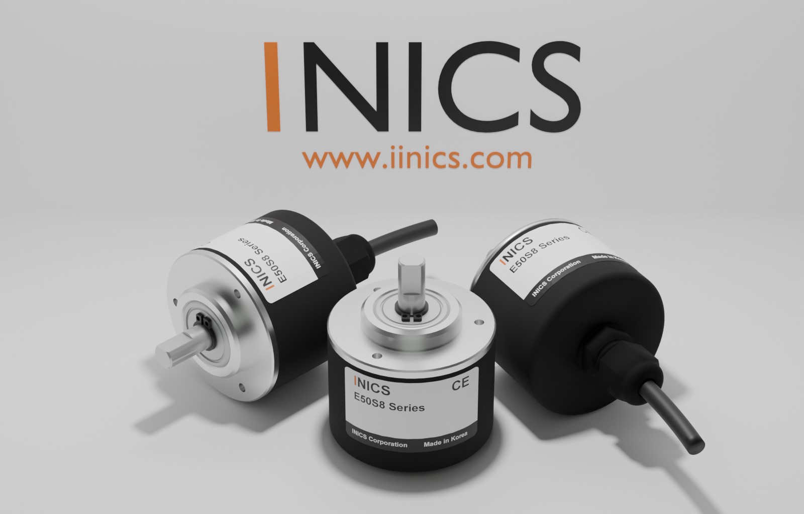
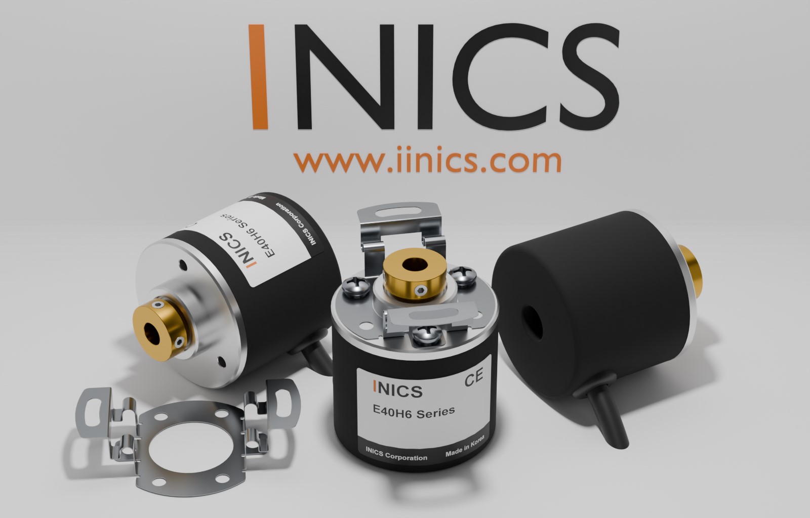
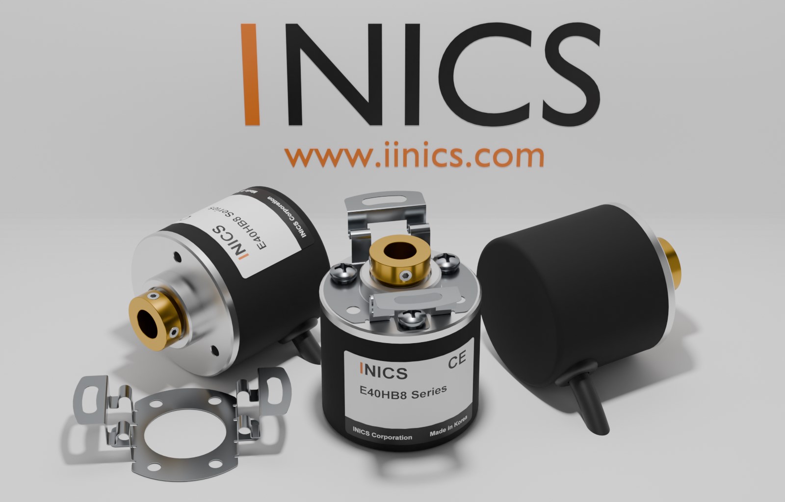
An optical incremental encoder reading rotation with an LED and
slit disk — where the INICS sensor business began. Three housings —
shaft, fully-open hollow and closed-end built-in — with
60–3600 P/R resolutions.
3,600 P/R
Max. Resolution
150 KHZ
Max. Response Freq.
5,000 RPM
Max. Speed
A·B·Z
Output Channels
Key Features
FEATURE 01
Proven Optical Sensing
An LED shining through a rotating slit disk generates clean pulses,
immune to magnetic interference — the technology INICS has refined
the longest.
FEATURE 02
14-Step Resolution Line-up
Fourteen resolutions from 60 to 3,600 P/R, including binary
256/1024, to match any control system.
FEATURE 03
A / B / Z Channels
Quadrature A/B for direction, plus a once-per-revolution Z index
for homing. x4 counting quadruples the effective resolution.
FEATURE 04
4 Output Types
Line driver adds differential A̅/B̅/Z̅ for long, noisy runs.
1 µs response (2 µs for NPN).
TOTEM POLENPN O.CVOLTAGELINE DRIVER
FEATURE 05
Aluminum or PA66-GF30 Body
Standard aluminum, or the lightweight high-rigidity PA66-GF30
plastic body (P model) with excellent wear, oil and fuel resistance.
FEATURE 06
Mounting Kit Included · CE
Coupling (shaft) or bracket (hollow/built-in) and bolts included.
50G shock, 5G vibration, -10 to 70 ℃, 1.5 m shielded cable.
CE certified.
Technology · Sensing Principle
LED + Slit Disk + Photo Detector
Interrupted Light Becomes Pulses
Each time LED light passes through the rotating slit disk, the photodetector converts the light ON/OFF into an electrical pulse. The number of slits on the disk is the resolution (P/R) — rotation angle is converted precisely into pulse count.
Slit count = resolution — one pulse per slit per revolution (60–3,600 P/R).
A/B 90° phase shift — the lead/lag of the two channels determines CW/CCW direction.
Z reference pulse — one pulse per revolution marks the home (zero) position.
Speed design formula — max. response speed (rpm) = 150 kHz ÷ resolution × 60 (within the 5,000 rpm limit).